Transmission components: essential guide to gear nomenclature
This guide gives you the basic terminology: what you need to read a datasheet, place a correct order, or understand why two gears can't be paired.
What a gear does
A gear is a mechanism that transmits motion, torque and force from one component to another inside a machine. Two or more gears combined form a gear transmission, in which the transmitted forces vary as a function of the wheel radii.
Conventional nomenclature distinguishes two basic elements of the pair: the smaller wheel is the pinion, the toothed wheel connected to the rotating source (the motor); the larger one is the gear wheel. The rack, by contrast, is a linear toothed element: a straight bar with teeth that, paired with the pinion, converts rotary motion into continuous linear movement.
When the two wheels have different diameters, the system lets you vary the transmission ratio: you can increase torque by reducing angular speed, or do the opposite, increase speed at the expense of transmitted torque.
Tooth geometry
The teeth develop radially from the pitch surface, a cylindrical reference surface that divides the tooth into two zones. The part that projects outward is the tooth tip; the inner portion, close to the wheel center, is the tooth root. The lateral surfaces of the tooth form its profile.
The profile divides into two parts relative to the pitch circle: the outer portion is called the face, the inner one the flank.
The main geometric quantities of the tooth are:
- Addendum: radial distance between the pitch diameter and the outside diameter of the gear.
- Dedendum: radial distance between the pitch diameter and the root diameter.
- Tooth height: sum of addendum and dedendum.
- Tooth pitch: distance measured along the circumference between two corresponding points on consecutive teeth.
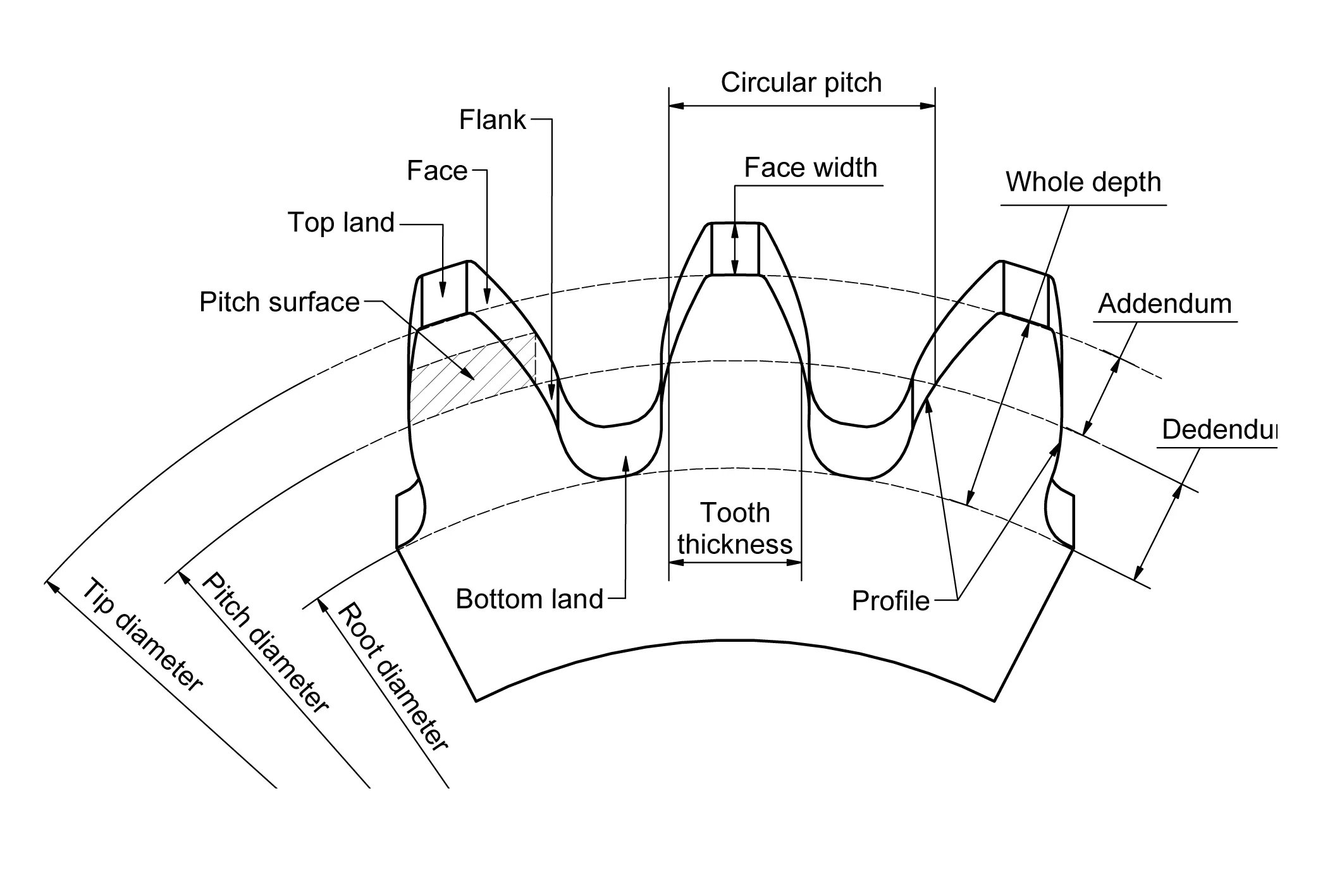
The involute profile
Among all existing tooth profiles, the most widespread in modern mechanical engineering is the involute profile. It is generated geometrically from a point on a straight line that unwinds while keeping tangent contact with a fixed circle throughout its motion.
The involute profile is preferred for two practical reasons: it guarantees uniform, regular meshing, tolerating variations in center distance without compromising operation; its production is simpler thanks to the use of standardized tools.
For correct meshing, two gears must have the same pitch on their pitch surfaces. In design terms, this means the same value of the module, the parameter that normalizes tooth dimensions relative to the number of teeth. Different modules: meshing impossible.
Reference quantities for design
Designing a gear transmission requires certain fundamental geometric quantities. The main ones are summarized here:
| Quantity | Symbol | Definition | Importance |
|---|---|---|---|
| Module | m | Ratio between pitch and π; parameter that defines tooth size and compatibility. | Ensures compatibility between different gears. |
| Pitch | p | Distance between two consecutive corresponding teeth measured along the pitch circle. | Determines tooth spacing and affects meshing. |
| Operating center distance | a | Distance between the centers of the pitch surfaces of the two paired wheels. | Critical for correct load distribution and pairing life. |
| Chordal distance (Wildhaber) | W | Measurement of pitch and tooth thickness taken with a micrometer over a defined number of teeth. | Practical method to verify tolerance conformity without complex instruments. |
The operating center distance is critical during assembly: a wrong value compromises force transmission and causes premature wear. The Wildhaber chordal distance, by contrast, is a simple inspection tool to check tooth accuracy and compliance with design tolerances.
The operating center distance is not a figure to estimate by eye. Even a small error during assembly translates into non-uniform load distribution and accelerated wear.
In the next guides
This guide covers basic nomenclature. In the following Technical Center guides you'll find detailed coverage of the different gear types (spur, helical, bevel, worm) and the selection criteria based on the specific application.
If you have doubts about terminology for a specific application or need support reading a datasheet, contact the technical office.